
3D Graphics
Basic Concepts
Points and Basis Vectors
Each point is a tuple of (x, y, z)
P = (x, y, z)
Each element is a scalar that defines a position along a Basis Vector.
Each basis vector has a unit length of exactly 1, (1, 1, 1) is even too long.
X = (1, 0, 0)
Y = (0, 1, 0)
Z = (0, 0, 1)
O = Origin Point of coordinate system
{O;X,Y,Z}
A points position in (x, y, z) is relative to the origin
Any point P,(a,b,c) can be represented as:
P = O + aX + bY + cZ
Example,(2, 3, 4) can be represented as:
P = O + 2X + 3Y + 4Z
P = (0,0,0) + (2,0,0) + (0,3,0) + (0,0,4)
Coordinate Axioms
Our coord system will have all axes as mutually perpendicular
Our coord system will be "right-handed" which means:
X = Cross Product of Y and Z
X = Y x Z
? Y = X x Z ? (guess)
? Z = X x Y ? (guess)
Cross Product of 3 tuples:
(a, b, c) x (d, e, f) = (b*f - c*e, c*d - a*f, a*e - b*d)
Point and Vector Rules
Points and Vectors are totally different: Point is a physical location in space Vector is the space between two points
Axiom 1: The difference between to points is a Vector, V = P - Q
Axiom 2: The sum of a point and a vector is a Point, Q = P + V
Example Structures
Point Class {
    tuple[3]; // (x,y,z)

    Point AddVectorToPoint(V);
    Point SubtractVectorFromPoint(V);
    Vector SubtractPointFromPoint(V);
}

Vector Class {
    tuple[3]; // (x,y,z)

    Vector AddVectorToVector(V);
    Vector SubtractVectorFromVector(V);
}
Linear Transformations
All linear transformations take this form:
B = F(A)
If you have a linear transformation funtion F() and your input vector is A then your output will be vector B
Each piece can be represented as a matrix, B as a 1x3 matrix, A as a 1x3 matrix and F as a 3x3 matric (called a Transformation Matrix)
Expanded it looks like:
[ b0 ]   [ f00 f01 f02 ] [ a0 ]
| b1 | = | f10 f11 f12 | | a1 |
[ b2 ]   [ f20 f21 f22 ] [ a2 ]
Rewritten as:
[ b0 ]   [ f00*a0 + f01*a1 + f02*a2 ]
| b1 | = | f10*a0 + f11*a1 + f12*a2 |
[ b2 ]   [ f20*a0 + f21*a1 + f22*a2 ]
These may be altered bby having a second input such as ingin rotations where a vector and rotation amount are given
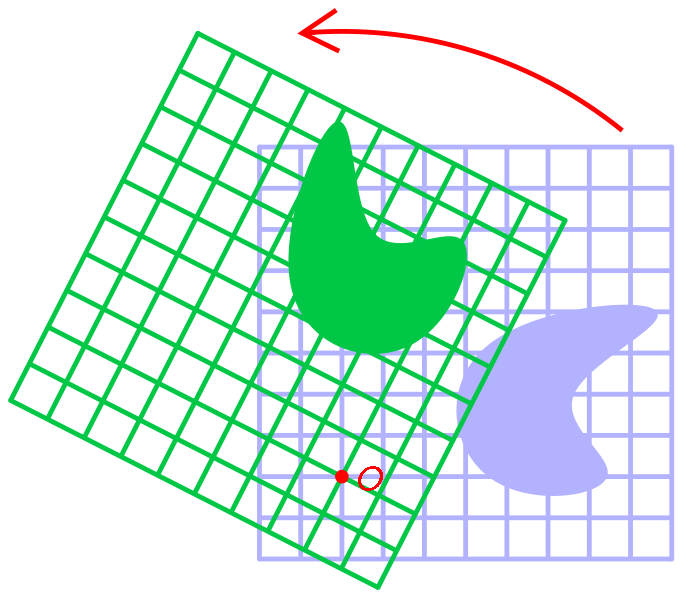
Rotations
Rotation is the circular movement of an object around a point of rotation
The point of rotation can be:
- the XY plane
- the XZ plane
- the YZ plane
Our three points of rotation each have a separate rotation matrix:
XY Rotation Matrix
[ cos(angle) -sin(angle) 0 ]
| sin(angle) -cos(angle) 0 |
[ 0          0           1 ]
XZ Rotation Matrix
[ cos(angle)  0 sin(angle) ]
| 0           1 0          |
[ -sin(angle) 0 cos(angle) ]
YZ Rotation Matrix
[ 1 0          0           ]
| 0 cos(angle) -sin(angle) |
[ 0 sin(angle) cos(angle)  ]
Rotating point A around the XY plane by 90 degrees (pi/2 radians) is:
[ b0 ]   [ cos(pi/2) -sin(pi/2) 0 ] [ a0 ]
| b1 | = | sin(pi/2) -cos(pi/2) 0 | | a1 ]
[ b2 ]   [ 0         0          1 ] [ a2 ]

         [ cos(pi/2)*a0 + -sin(pi/2)*a1 + 0*a2 ]
       = | sin(pi/2)*a0 + -cos(pi/2)*a1 + 0*a2 |
         [ 0*a0         + 0*a1          + 1*a2 ]

         [ 0*a0 + -1*a1 + 0*a2 ]
       = | 1*a0 + 0*a1  + 0*a2 |
         [ 0*a0 + 0*a1  + 1*a2 ]
These rotation angles can be added to our vector class as functions:
Vector rotateVectoronXYPlane(angle);
Vector rotateVectoronXZPlane(angle);
Vector rotateVectoronYZPlane(angle);
Scaling
Simpler than rotations, a scaling transformation requires and input vector and a scaling 3-tuple
A scaling tuple (s0,s1,s2)
The scaling matrix becomes:
[ s0  0   0  ]
| 0   s1  0  |
[ 0   0   s2 ]
We can make input vector A twice its size along the X acis by scaling it with S = (2,1,1)
[ b0 ]   [ s0  0   0  ] [ a0 ]
| b1 | = | 0   s1  0  | | a1 |
[ b2 ]   [ 0   0   s2 ] [ a2 ]

         [ 2 0 0 ] [ a0 ]
       = | 0 1 0 ] | a1 |
         [ 0 0 1 ] [ a2 ]

       ...

         [ 2*a0 ]
       = | 1*a1 |
         [ 1*a2 ]
So input A=(3,4,0) would become B=(6,4,0)
This can be added as a function to our vector class
Vector scaleVector(s0, s1, s2);Translation
This needs to be covered
Camera
Cameras consist of two parts that allow for transforming world vertices to a screen: the external part and internal part.
The external part will translate a vertex from world space to the 3D camera space. It is essentially the same as positioning the camera inside the world (but in reality it is shifting the world around the camera).
The internal part will tranform the camera coordinate system to the screen, aka perspective projection.
Camera Transformation Matrix
The transformation that places the camera in the correct position in world space
It is applied to the 3D model of the camera to move it about and rotate it etc
A transformation matrix is 4x4
- first column is the X vector (right) - X
- second column is the Y vector (up) - Y
- third column is the Z vector (forward) - Z
- fourth column is the translation vector (position in space) - W
M = [ Xx Yx Zx Wx ]
    | Xy Yy Zy Wy |
    [ Xz Yz Zz Wz |
    [ 0  0  0  1  ]
In order to transform a vector (V) by the transformation matrix (M) we must premultiply it:
t = vector tranformed
v = vector
M = transformation matrix
If R represents the orientation of the camera, and T represents the translation of the camera in world space, then the cameras transform matrix M can be computed:
M = TR - first rotate then translate
The View Matrix
This matrix will transform vertices from world space to view space
It is the inverse of the transformation matrix
If M represents the objects world matrix, and V represents the view matrix and P is the projection matrix, then the world, view, projection matrix can be represented by MVP
MVP = P * V * M
A vertex v can be transformed to the screen space sv by
sv = MVP * v
View Matrix
The external part of the camera
It is a 4x4 matrix that is made up of a 3x3 rotation matrix and a 1x4 translation matrix.
The rotation matrix determines camera orientation, an translation matrix determines the cameras position in the world.
Projection Matrix
The internal part of a maera is called a Projection Matrix
It maps the 3D coordinate to a 2D screen coordinate
Xs = x on screen
Ys = y on screen
Fx, Fy = aspect ratio (e.g. 4/3, 16/9)
S = skew parameter ?
Xo, Yo = focal length ?
[ xS ] [ Fx S Xo ] [ Xc ]
| yS | = | 0 Fy Yo | | Yc |
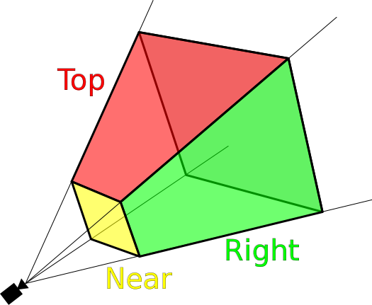
[ 1 ] [ 0 0 1 ] [ Zc ]London Culling
We can set parameters of a view space to cull points outside of our view.
Our View Space:
- defined across x, y and z axes
- x will consit of everything between the windows left and right boundaries
- y all between windows top and bottom
- z between 0 (where camera is set) and our players view distance
Before drawing a point our camera class will check if that point lies within our view.
Camera Definition
Camera Class {
    // boundaries
    minX, maxX
    minY, maxY
    minZ, maxZ
}
Each draw cycle we will compare all points to the camera's culling parameters and draw them if they are within
A Renderer class can do this logic so as to not clutter the camera with rendering
Point Management
Refs:
- https://gamedevelopment.tutsplus.com/tutorials/lets-build-a-3d-graphics-engine-linear-transformations--gamedev-7716
- https://gamedev.stackexchange.com/questions/61406/what-is-the-logic-behind-a-3d-projection-camera-perspective
- https://www.3dgep.com/understanding-the-view-matrix/
- https://medium.com/retronator-magazine/game-developers-guide-to-graphical-projections-with-video-game-examples-part-1-introduction-aa3d051c137d